10.1 带有观察点的相机模型
初始设置
让我们创建一个新的着色器,并添加以下我们将用于本教程的样板代码。请注意现在如何在代码顶部定义常量。
// Constants
const int MAX_MARCHING_STEPS = 255;
const float MIN_DIST = 0.0;
const float MAX_DIST = 100.0;
const float PRECISION = 0.001;
const float EPSILON = 0.0005;
const float PI = 3.14159265359;

// Rotation matrix around the X axis.
mat3 rotateX(float theta) {
    float c = cos(theta);
    float s = sin(theta);
    return mat3(
        vec3(1, 0, 0),
        vec3(0, c, -s),
        vec3(0, s, c)
    );
}

// Rotation matrix around the Y axis.
mat3 rotateY(float theta) {
    float c = cos(theta);
    float s = sin(theta);
    return mat3(
        vec3(c, 0, s),
        vec3(0, 1, 0),
        vec3(-s, 0, c)
    );
}

// Rotation matrix around the Z axis.
mat3 rotateZ(float theta) {
    float c = cos(theta);
    float s = sin(theta);
    return mat3(
        vec3(c, -s, 0),
        vec3(s, c, 0),
        vec3(0, 0, 1)
    );
}

// Identity matrix.
mat3 identity() {
    return mat3(
        vec3(1, 0, 0),
        vec3(0, 1, 0),
        vec3(0, 0, 1)
    );
}

struct Surface {
    float sd; // signed distance value
    vec3 col; // color
};

Surface sdBox( vec3 p, vec3 b, vec3 offset, vec3 col, mat3 transform)
{
  p = (p - offset) * transform; // apply transformation matrix
  vec3 q = abs(p) - b;
  float d = length(max(q,0.0)) + min(max(q.x,max(q.y,q.z)),0.0);
  return Surface(d, col);
}

Surface sdFloor(vec3 p, vec3 col) {
  float d = p.y + 1.;
  return Surface(d, col);
}

Surface minWithColor(Surface obj1, Surface obj2) {
  if (obj2.sd < obj1.sd) return obj2;
  return obj1;
}

Surface sdScene(vec3 p) {
  vec3 floorColor = vec3(1. + 0.7*mod(floor(p.x) + floor(p.z), 2.0));
  Surface co = sdFloor(p, floorColor);
  co = minWithColor(co, sdBox(p, vec3(1), vec3(-4, 0.5, -4), vec3(1, 0, 0), identity())); // left cube
  co = minWithColor(co, sdBox(p, vec3(1), vec3(0, 0.5, -4), vec3(0, 0.65, 0.2), identity())); // center cube
  co = minWithColor(co, sdBox(p, vec3(1), vec3(4, 0.5, -4), vec3(0, 0.55, 2), identity())); // right cube
  return co;
}

Surface rayMarch(vec3 ro, vec3 rd, float start, float end) {
  float depth = start;
  Surface co; // closest object

  for (int i = 0; i < MAX_MARCHING_STEPS; i++) {
    vec3 p = ro + depth * rd;
    co = sdScene(p);
    depth += co.sd;
    if (co.sd < PRECISION || depth > end) break;
  }

  co.sd = depth;

  return co;
}

vec3 calcNormal(in vec3 p) {
    vec2 e = vec2(1, -1) * EPSILON;
    return normalize(
      e.xyy * sdScene(p + e.xyy).sd +
      e.yyx * sdScene(p + e.yyx).sd +
      e.yxy * sdScene(p + e.yxy).sd +
      e.xxx * sdScene(p + e.xxx).sd);
}

void mainImage( out vec4 fragColor, in vec2 fragCoord )
{
  vec2 uv = (fragCoord-.5*iResolution.xy)/iResolution.y;
  vec3 backgroundColor = vec3(0.835, 1, 1);

  vec3 col = vec3(0);
  vec3 ro = vec3(0, 0, 3); // ray origin that represents camera position
  vec3 rd = normalize(vec3(uv, -1)); // ray direction

  Surface co = rayMarch(ro, rd, MIN_DIST, MAX_DIST); // closest object

  if (co.sd > MAX_DIST) {
    col = backgroundColor; // ray didn't hit anything
  } else {
    vec3 p = ro + rd * co.sd; // point on cube or floor we discovered from ray marching
    vec3 normal = calcNormal(p);
    vec3 lightPosition = vec3(2, 2, 7);
    vec3 lightDirection = normalize(lightPosition - p);

    float dif = clamp(dot(normal, lightDirection), 0.3, 1.); // diffuse reflection

    col = dif * co.col + backgroundColor * .2; // Add a bit of background color to the diffuse color
  }

  // Output to screen
  fragColor = vec4(col, 1.0);
}
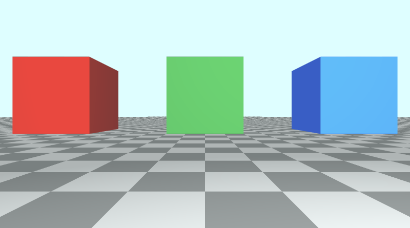
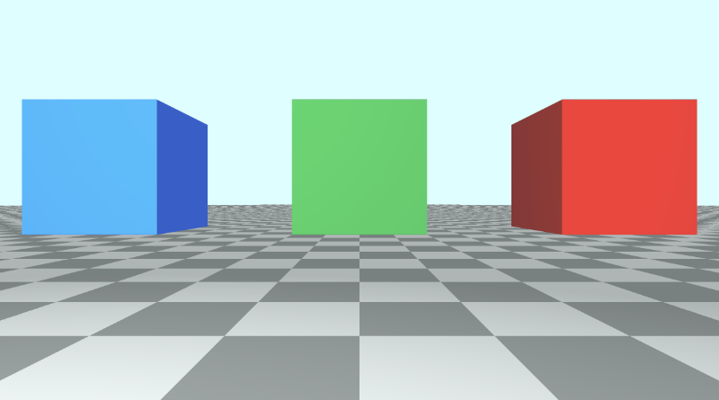
此代码将生成一个包含三个立方体的场景,每个立方体具有不同的颜色:红色、绿色和蓝色。
LookAt 点
目前,当我们想要移动相机时,我们必须调整光线原点的值。要倾斜相机,我们需要将光线方向乘以旋转矩阵。
另一种方法是创建一个接受相机位置(或光线原点)和注视点的相机函数。然后,此函数将返回一个 3x3 变换矩阵,我们可以将光线方向乘以该矩阵。
mat3 camera(vec3 cameraPos, vec3 lookAtPoint) {
    vec3 cd = normalize(lookAtPoint - cameraPos); // camera direction
    vec3 cr = normalize(cross(vec3(0, 1, 0), cd)); // camera right
    vec3 cu = normalize(cross(cd, cr)); // camera up

    return mat3(-cr, cu, -cd);
}
要了解我们是如何得出这个矩阵的,让我们看看下图。它是在网站 Learn OpenGL 上创建的,该网站是学习 OpenGL 图形 API 的绝佳资源。
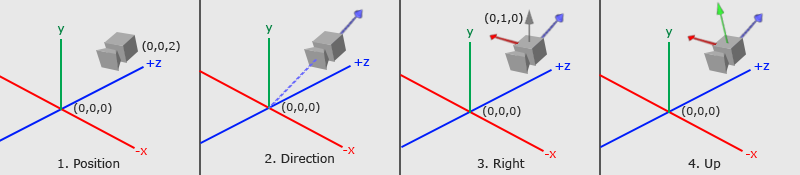
由 Learn OpenGL 提供的摄像机/视图空间 提供
上图传达了很多关于 3x3 矩阵是如何创建的。我们需要通过分析三个重要的摄��像机向量来弄清楚摄像机的观察位置以及它的倾斜方式:Camera direction向量、Camera right向量和 Camera up 向量。
在第 1 步中,我们从相机位置cameraPos开始,该位置等于代码中的光线原点 ro。
在第 2 步中,我们创建一个相对于 lookat 点的相机方向向量。在图像中,观察点位于 3D 空间中的原点,但我们可以将此点移动到任何我们想要的任何位置。请注意摄像机方向如何指向远离摄像机的方向。这意味着它使用了我们在 第 6 部分 中了解的右手定则。
vec3 cd = normalize(lookAtPoint - cameraPos); // camera direction
在步骤 3 中,有一个灰色矢量从摄像机直接指向上方。方向向量 (0, 1, 0) 表示 y 轴的单位向量。我们通过取 y 轴的单位向量和相机方向之间的叉积来创建“相机右”向量。这将创建指向摄像机右侧的红色矢量。
normalize(cross(vec3(0, 1, 0), cd)); // camera right
在第 4 步中,我们通过取相机方向向量和 camera right 向量之间的叉积来找到 camera up 向量。此“相机向上”矢量在图像中由从相机伸出的绿色矢量表示。
vec3 cu = normalize(cross(cd, cr)); // camera up
最后,我们通过将这些向量组合在一起来创建一个转换矩阵:
mat3 camera(vec3 cameraPos, vec3 lookAtPoint) {
    vec3 cd = normalize(lookAtPoint - cameraPos); // camera direction
    vec3 cr = normalize(cross(vec3(0, 1, 0), cd)); // camera right
    vec3 cu = normalize(cross(cd, cr)); // camera up

    return mat3(-cr, cu, -cd); // negative signs can be turned positive (or vice versa) to flip coordinate space conventions
}
让我们看看 camera 函数的 return 语句:
return mat3(-cr, cu, -cd);
正负从何而来?由我们来定义一个约定,即如何标记 3D 空间中每个轴的正方向或负方向。这是我将在本教程中使用的约定。我们很快就会看到当我们翻转方向时会发生什么。
应用相机矩阵
现在我们已经创建了一个 camera 函数,让我们在 mainImage 函数中使用它。我们将创建一个 lookat 点并将其传递给 camera 函数。然后,我们将它返回的矩阵乘以光线方向,类似于我们在第 9 部分中所做的。
vec3 lp = vec3(0, 0, 0); // lookat point (aka camera target)
vec3 ro = vec3(0, 0, 3); // ray origin that represents camera position
vec3 rd = camera(ro, lp) * normalize(vec3(uv, -1)); // ray direction
当您运行代码时,场景看起来应该几乎相同。但是,摄像机现在以 3D 空间中的原点为目标。由于立方体离地面 0.5 个单位,因此摄像机会从中心略微倾斜。我们可以通过更改注视点来匹配绿色立方体的位置,从而将相机直接对准绿色立方体的中心。
vec3 lp = vec3(0, 0.5, -4);
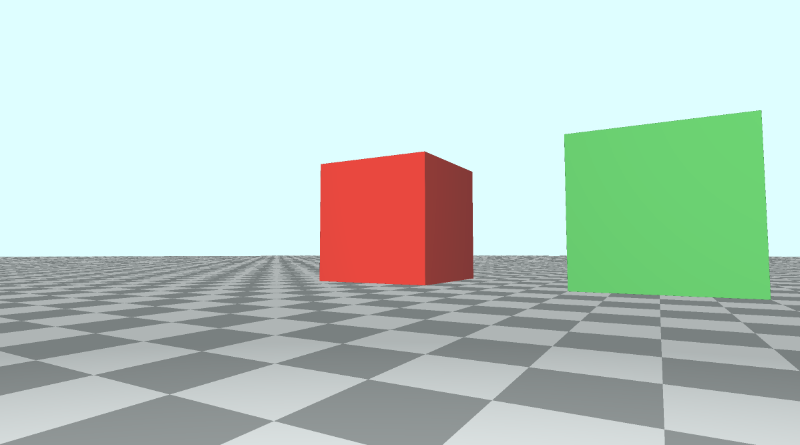
假设我们现在想查看红色立方体。它目前在 3D 空间中的位置为 (-4, 0.5, -4)。让我们更改 lookat 点以匹配该位置。
vec3 lp = vec3(-4, 0.5, -4);
您应该看到摄像机现在指向红色立方体,并且它应该位于画布的中心。
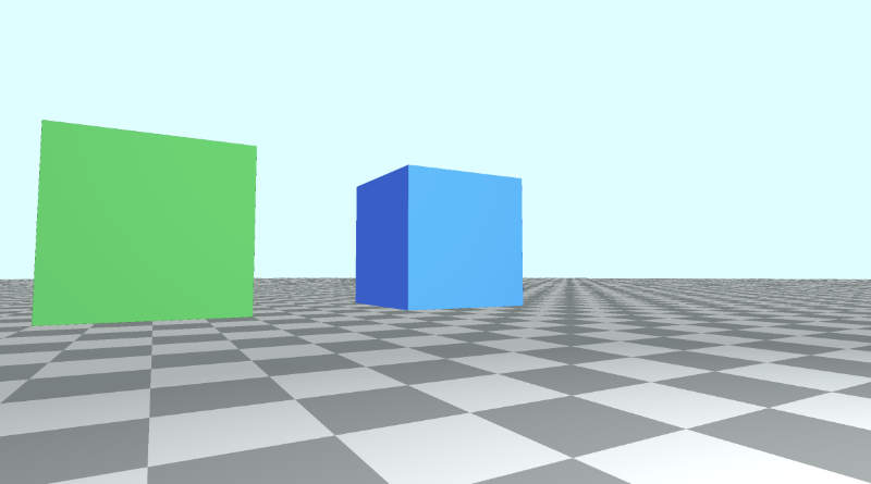
现在让我们看看蓝色立方体。它在 3D 空间中的位置为 (4, 0.5, -4),因此我们将 lookat point 更改为等于该值。
vec3 lp = vec3(4, 0.5, -4);
您应该看到摄像机现在指向蓝色立方体,并且它应该位于画布的中心。
您可以在下面找到完成的代码:
// Constants
const int MAX_MARCHING_STEPS = 255;
const float MIN_DIST = 0.0;
const float MAX_DIST = 100.0;
const float PRECISION = 0.001;
const float EPSILON = 0.0005;
const float PI = 3.14159265359;

// Rotation matrix around the X axis.
mat3 rotateX(float theta) {
    float c = cos(theta);
    float s = sin(theta);
    return mat3(
        vec3(1, 0, 0),
        vec3(0, c, -s),
        vec3(0, s, c)
    );
}

// Rotation matrix around the Y axis.
mat3 rotateY(float theta) {
    float c = cos(theta);
    float s = sin(theta);
    return mat3(
        vec3(c, 0, s),
        vec3(0, 1, 0),
        vec3(-s, 0, c)
    );
}

// Rotation matrix around the Z axis.
mat3 rotateZ(float theta) {
    float c = cos(theta);
    float s = sin(theta);
    return mat3(
        vec3(c, -s, 0),
        vec3(s, c, 0),
        vec3(0, 0, 1)
    );
}

// Identity matrix.
mat3 identity() {
    return mat3(
        vec3(1, 0, 0),
        vec3(0, 1, 0),
        vec3(0, 0, 1)
    );
}

struct Surface {
    float sd; // signed distance value
    vec3 col; // color
};

Surface sdBox( vec3 p, vec3 b, vec3 offset, vec3 col, mat3 transform)
{
  p = (p - offset) * transform; // apply transformation matrix
  vec3 q = abs(p) - b;
  float d = length(max(q,0.0)) + min(max(q.x,max(q.y,q.z)),0.0);
  return Surface(d, col);
}

Surface sdFloor(vec3 p, vec3 col) {
  float d = p.y + 1.;
  return Surface(d, col);
}

Surface minWithColor(Surface obj1, Surface obj2) {
  if (obj2.sd < obj1.sd) return obj2;
  return obj1;
}

Surface sdScene(vec3 p) {
  vec3 floorColor = vec3(1. + 0.7*mod(floor(p.x) + floor(p.z), 2.0));
  Surface co = sdFloor(p, floorColor);
  co = minWithColor(co, sdBox(p, vec3(1), vec3(-4, 0.5, -4), vec3(1, 0, 0), identity())); // left cube
  co = minWithColor(co, sdBox(p, vec3(1), vec3(0, 0.5, -4), vec3(0, 0.65, 0.2), identity())); // center cube
  co = minWithColor(co, sdBox(p, vec3(1), vec3(4, 0.5, -4), vec3(0, 0.55, 2), identity())); // right cube
  return co;
}

Surface rayMarch(vec3 ro, vec3 rd, float start, float end) {
  float depth = start;
  Surface co; // closest object

  for (int i = 0; i < MAX_MARCHING_STEPS; i++) {
    vec3 p = ro + depth * rd;
    co = sdScene(p);
    depth += co.sd;
    if (co.sd < PRECISION || depth > end) break;
  }

  co.sd = depth;

  return co;
}

vec3 calcNormal(in vec3 p) {
    vec2 e = vec2(1, -1) * EPSILON;
    return normalize(
      e.xyy * sdScene(p + e.xyy).sd +
      e.yyx * sdScene(p + e.yyx).sd +
      e.yxy * sdScene(p + e.yxy).sd +
      e.xxx * sdScene(p + e.xxx).sd);
}

mat3 camera(vec3 cameraPos, vec3 lookAtPoint) {
    vec3 cd = normalize(lookAtPoint - cameraPos); // camera direction
    vec3 cr = normalize(cross(vec3(0, 1, 0), cd)); // camera right
    vec3 cu = normalize(cross(cd, cr)); // camera up

    return mat3(-cr, cu, -cd);
}

void mainImage( out vec4 fragColor, in vec2 fragCoord )
{
  vec2 uv = (fragCoord-.5*iResolution.xy)/iResolution.y;
  vec3 backgroundColor = vec3(0.835, 1, 1);

  vec3 col = vec3(0);
  vec3 lp = vec3(4, 0.5, -4); // lookat point (aka camera target)
  vec3 ro = vec3(0, 0, 3); // ray origin that represents camera position
  vec3 rd = camera(ro, lp) * normalize(vec3(uv, -1)); // ray direction

  Surface co = rayMarch(ro, rd, MIN_DIST, MAX_DIST); // closest object

  if (co.sd > MAX_DIST) {
    col = backgroundColor; // ray didn't hit anything
  } else {
    vec3 p = ro + rd * co.sd; // point on cube or floor we discovered from ray marching
    vec3 normal = calcNormal(p);
    vec3 lightPosition = vec3(2, 2, 7);
    vec3 lightDirection = normalize(lightPosition - p);

    float dif = clamp(dot(normal, lightDirection), 0.3, 1.); // diffuse reflection

    col = dif * co.col + backgroundColor * .2; // Add a bit of background color to the diffuse color
  }

  // Output to screen
  fragColor = vec4(col, 1.0);
}
调整正负方向的约定
之前,我们看到 camera 函数返回一个由三个相机向量组成的矩阵。
mat3 camera(vec3 cameraPos, vec3 lookAtPoint) {
    vec3 cd = normalize(lookAtPoint - cameraPos); // camera direction
    vec3 cr = normalize(cross(vec3(0, 1, 0), cd)); // camera right
    vec3 cu = normalize(cross(cd, cr)); // camera up

    return mat3(-cr, cu, -cd);
}
如果我们设置 Lookat 点以将相机对准绿色立方体,则有以下代码:
vec3 lp = vec3(0, 0.5, -4); // lookat point (aka camera target)
vec3 ro = vec3(0, 0, 3); // ray origin that represents camera position
vec3 rd = camera(ro, lp) * normalize(vec3(uv, -1)); // ray direction
这将生成本教程开头的场景,其中红色立方体位于绿色立方体的左侧,蓝色立方体位于绿色立方体的右侧。
如果我们决定在 camera 函数中使用正的 cr 值,那么让我们看看会发生什么。
红色立方体和蓝色立方体似乎交换了位置,但要注意地砖。他们也被调换了。摄像机右侧矢量是相反的,这会导致整个场景翻转,就像查看原始场景的镜像一样。
使用正 cr 会影响相机看到的内容,也会使我们的立方体的位置看起来令人困惑。我们的 x 轴设计为画布中心的左侧为负值,中心右侧的正值。翻转 cr 也意味着翻转那个约定。
如果我们将相机方向的值 cd 反转为正值而不是负值,它会转动相机,因为它会翻转我们的 z 轴约定。
翻转 z 轴约定的另一种方法是对光线方向的 z 分量使用正值。
vec3 rd = normalize(vec3(uv, 1)); // positive one is being used instead of negative one
当您将这种替代相机模型与注视点一起使用时,最好了解您为每个轴上的正或负设置的约定。
你可以尝试使用 cr、cu 和 cd 来制作一些有趣的效果。确保将光线方向 rd,改回使用负 1。
以下代码可以在 z 轴上创建 slingshot 效果,使其看起来像是摄像机非常快速地缩小和放大。也许这可以用来创造 warp drive 效果?🤔
mat3 camera(vec3 cameraPos, vec3 lookAtPoint) {
    vec3 cd = normalize(lookAtPoint - cameraPos); // camera direction
    vec3 cr = normalize(cross(vec3(0, 1, 0), cd)); // camera right
    vec3 cu = normalize(cross(cd, cr)); // camera up

    return mat3(-cr, cu, abs(cos(iTime)) * -cd);
}
继续将相机矩阵更改回正常,然后再继续本教程的下一部分。
mat3 camera(vec3 cameraPos, vec3 lookAtPoint) {
    vec3 cd = normalize(lookAtPoint - cameraPos); // camera direction
    vec3 cr = normalize(cross(vec3(0, 1, 0), cd)); // camera right
    vec3 cu = normalize(cross(cd, cr)); // camera up

    return mat3(-cr, cu, -cd);
}